ELE202 - Black Box Lab Tutorial
----------------2013 Version ----------------------
Notice, all the instruction here is just for tutorial purpose,
please followed up with you own instructor for the Rule and Instruction for your Lab Test.
1. General Information : The time / place for the Lab Test and Lab Clinic (Notice: all Lab Clinic are finished)
6. Analysis, Measurement and Calculation
Lab Clinic :
All 5 shifts of Lab Clinic (each 3 hours) are finished, more than 150 students show-up, wish you all success in the Lab Test. :)
The purpose of Lab Clinic is to give you a chance to practice.
You may come at the time when you are free, please study the theory part before you come.
|
Date |
Time |
Place |
|
Apr 3, 2013 (Wed) |
8:00AM to 11:00AM |
ENG302 |
| Apr 4, 2013 (Thu) | 2:00PM to 5:00PM | ENG301 or ENG302 * |
|
Apr 5, 2013 (Fri) |
8:00AM to 11:00AM |
ENG301 |
|
Apr 5, 2013 (Fri) |
11:00AM to 2:00PM |
ENG301 |
|
Apr 5, 2013 (Fri) |
2:00PM to 5:00PM |
ENG301 |
Lab Test:
Week of April 8 to April 12, 2013
Odd section (1, 3, 5, 7, 9, 11) : Same as your regular Lab schedule time
Even section (2, 4, 6, 8, 10, 12) : You need to signed up for a time to do your Lab Test (the signed-up sheet is in ENG301)
For the Lab Clinic:
1) Oscilloscope (you need to use both Channel 1 and Channel 2)
2) Function Generator
3) 2 x Decade Resistance Box (our Test Resistor / set it to 20 ohms)
4) 3 x Wires (the short one is good, you don't need the long one)
5) 1 x Capacitor Decade Box
6) 1 x Inductor Decade Box
* Remember, you don't need to use the DMM.
For the Lab Test
1) Oscilloscope (you need to use both Channel 1 and Channel 2)
2) Function Generator
3) Decade Resistance Box (our Test Resistor / set it to 20 ohms)
4) 1 Wire (the short one is good, you don't need the long one)
5) Black Box
* You may not need to use the DMM (Digital Multimeter) base on your professor's instruction (Winter 2014)
For the Lab Clinic
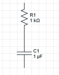
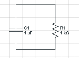
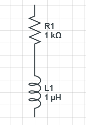
First, build your own Black Box by using 1 Resistor and 1 Capacitor or 1 Inductor. In either Series or Parallel.
Second, connect your Function Generator's (+) side to the other side of your Black Box (simulate one), and connect
your Function Generator's (–) side to the end of your Test Resistor;
Third, connect one of the Channel from Oscilloscope between the beginning point of the Black Box and the end point of Test Resistor;
Fourth, connect another Channel from Oscilloscope between the beginning point of the Test Resistor and the end point;
Finished
Demo Video : Black Box Lab Test - Lab Clinic - Part 1 - Setup (by Kevin)
* The connection in this video is ONLY for Lab Clinic, no need to remember it, you will get a Black Box for your lab test.
For the Lab Test
First, connect your Black Box (any side) to Test Resistor (use your short wire);
Second, connect your Function Generator's (+) side to the other side of your Black Box, and connect
your Function Generator's (–) side to the end of your Test Resistor;
Third, connect one of the Channel from Oscilloscope between the beginning point of the Black Box and the end point of Test Resistor;
Fourth, connect another Channel from Oscilloscope between the beginning point of the Test Resistor and the end point;
Finished
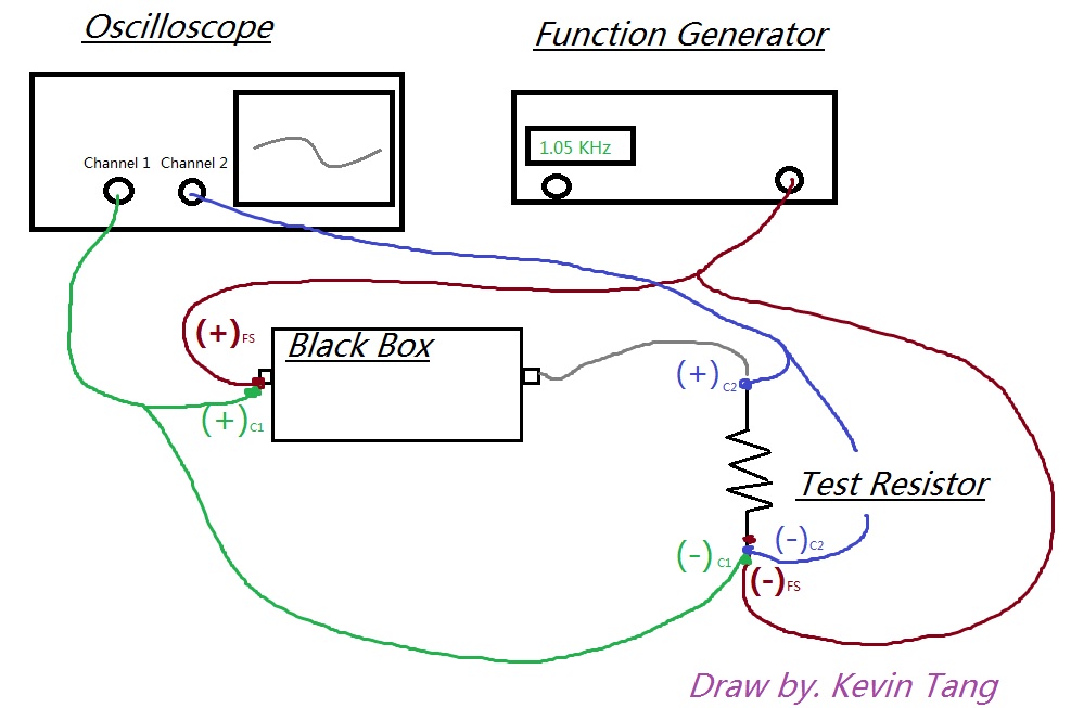
Example of how to connect the circuit in the Lab Test
BLACK BOX CONNECTION DIAGRAM
This connection is very important, please try to understand it,
this will be how you actually connect the circuit during your lab test.
Common Questions:
Why do we need Test Resistor?
Why the value for Test Resistor need to be small?
The voltage across the test resistor (channel 2 for my case), also shown on oscilloscope, is that directly equal to current?
1) We need test resistor to find out what is the current go through the black box.
2) Because if you choice a large test resistor value (e.g. 10kΩ), it will affect your voltage value on Channel 1,
which will make your calculation became more difficult later, so please set test resistor to a small value,
you may set your test resistor value around 20Ω~50Ω.
3) No, it is not directly equal to current, voltage does NOT equal to current, but this voltage is directly relate to our total current.
because if you look at the graph above, entire current come out from the black box go into the test resistor,
therefore, if you div this voltage (across test resistor) by the test resistor (V = RI), you can get current (I) easily
Example: You got 20 V pk to pk on current channel, and your test resistor is 20Ω, find I (current)?
Answer: Vi = 20 [v] pk-pk / 2 = 10 [v] pk ... remember to div by 2 to get peak voltage
I = Vi / Rtest
= 10V / 20Ω
= 0.5 [A]
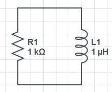
The characteristic of RC Series / Parallel and RL Series / Parallel you should know before you start.
| RC Series | RC Parallel | RL Series | RL Parallel | |
| Inside Black Box Connection
(The value are just for reference purpose) |
 |
 |
 |
 |
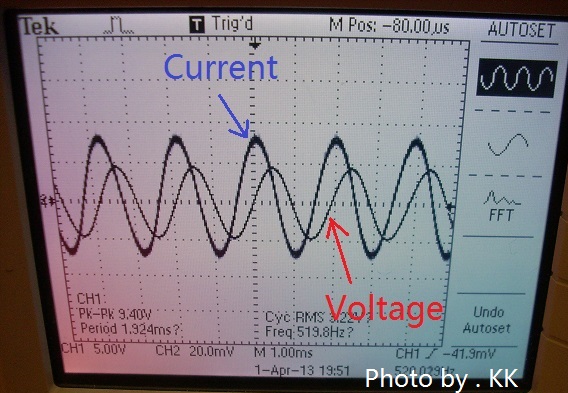
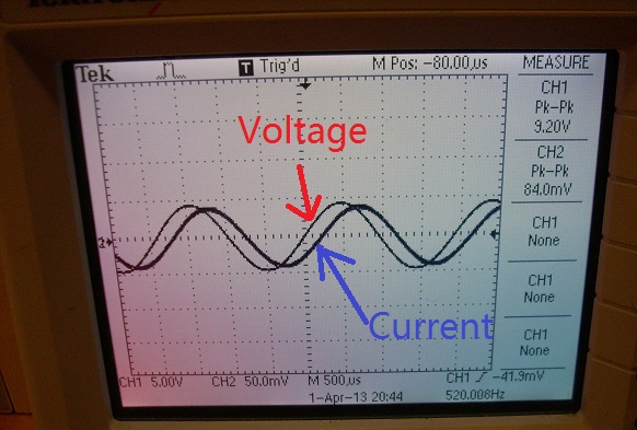
| Waveform | Current lead Voltage | Current lead Voltage | Voltage lead Current | Voltage lead Current |
|
Waveform Result |
|
|
|
|
|
Frequency and Phase |
Increasing Frequency cause Phase Difference to Decrease F Φ
|
Increasing Frequency will cause Phase Difference to Increase F Φ |
Increasing Frequency will cause Phase Difference to Increase F Φ |
Increasing Frequency cause Phase Difference to Decrease F Φ |
|
Example of Calculation (Thanks to Mr. Dewan Hammad)
*Notice, all the value of R, C and L are random, just to show you how to calculate it. |
RCS Calculation R = 2.5kΩ, C = 0.4uF
|
RCP Calculation R = 2.5kΩ, C = 0.4uF
|
RLS Calculation R = 2kΩ, L = 0.1H
|
RLP Calculation R = 2kΩ, L = 0.1H
|
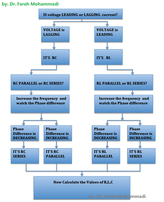
from course coordinator professor Dr. Farah Mohammadi
VERY USEFUL, read it and follow it step by step for your Lab Test.
 |
6. Analysis, Measurement and Calculation
Everything you need to know is been taught during the class time,
suggest that you review it before you start the Lab Clinic and Lab Test.
By the end of analysis, you should able to tell if the circuit in the Black Box
is RC Series, RC Parallel, RL Series or RL Parallel.
One thing you must remember for the Lab Test this year,
you are NOT ALLOWED to use DC ANALYSIS to analysis the circuit.
VERY IMPORTANT - Read the following two comments before you watch the Demo Video...
1. To measure phase difference: before measuring the number of blocks
, you should find the ground of each channel (by pushing the button for
ground-there are 3 options: AC,DC,GND) match them together, and then put
it back to AC and measure the phase difference.
2.When you increase the Frequency, just to see is if the phase difference
is increasing or decreasing is enough. You don't need to obtain the exact
measurement of the phase difference for 2 frequencies. However to find the
values of R,C or L you need to find the exact phase difference for one
frequency.
Demo Video : Black Box Lab Test - Lab Clinic - Part 2 - Analysis and Measurements (by Kevin)
The case when you have Inductor (RL Circuit)
Demo Video : Black Box Lab Test - Lab Clinic - Part 3 - RL Part (by Kevin)
Useful equation:
In Series case ... (you should understand the theory part by REVIEW your Course Notes)
In Parallel case...
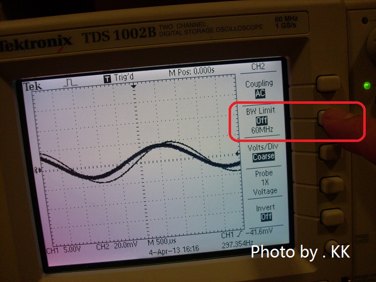
Q1: I got some noise in the wave signal I got, what can I do to reduce the noise? (see the diagram below)
A1:
1st - Press the CH1 or CH2 (depend on which channel you get the noise)
2nd - Press the BW Limit , changed it from 60MHz (Off) to 20MHz (On)
|
Before The noise is kind big (the very thick line)
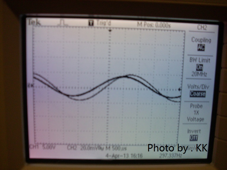
|
After The noise reduce.
|
Q2: I pressed so many wrong button, I couldn't get back even I press AUTOSET, even restart the oscilloscope, the problem still not able to solve.
A2:
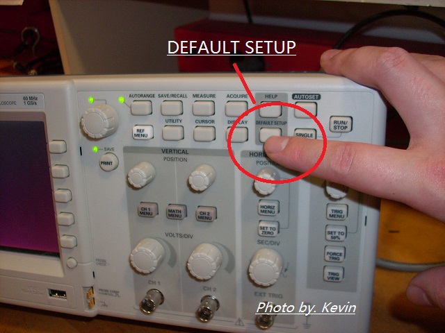
You can try to use "DEFAULT SETUP" button,
wait 3~5 sec until it recover the default setting,
once you get your default setting, remember to changed the Attenuation (Probe 10x) back to (Probe 1x) for both Channel 1 and Channel 2.
(See the diagram below)
|
Step#1 : Press the DEFAULT SETUP button
|
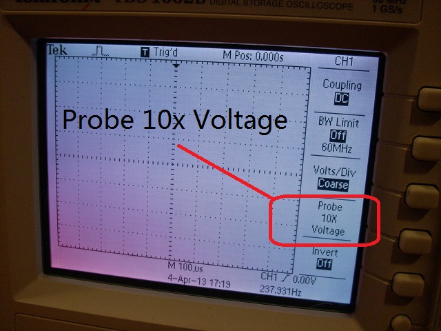
Step#2: Check if its shows Probe 10x on the Channel Screen, if it does, Change back to 1x for both CH1 and CH2
|
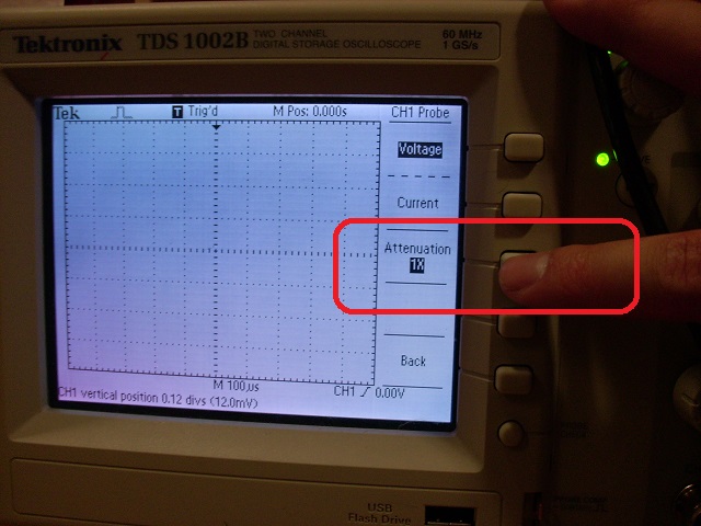
Step#3: Press the button, change back to Probe 1x. Finished.
|
Q3: What can I do if I don't get the waveform I want?
A3:
1st - Check Function Generator - you should put it at Sine Wave, sometimes you may set it wrong to Triangular Wave or Square Wave.
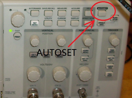
2nd - Press "AUTOSET" button, to see if problem solved.
3rd - Check your connection and ground setting.
Notice: AUTOSET button is very useful, use it wisely.
|
AUTOSET button
|
Q4 : I kept getting the wrong answer, and its seems to be 10 times bigger than the expected result, what did I do wrong?
A4 : On the Lab Clinic on Friday (Apr 5), we have 2 group run to the same problem, its not easy to catch this kind error,
it is highly possible because your Attenuation setting is "Probe 10x Voltage" instead "Probe 1x Voltag"e. (The correct setting is Probe 1x Voltage)
To changed back, just follow the diagrams shown below.
|
Step #1 - Check the menu on CH1 and CH2, if it shows Probe 10x Voltage, you need to change back to 1x.
|
Step# 2 - Changed the Attenuation back to 1x, finished.
|
Message for Facebook
You may leave me message if you have any questions, I will try to answer ASAP, thanks and good luck :)
by . Dr. Mohammadi and Kevin
Apr 2, 2013