Lab Tutorial Date
Extra Lab Tutorial for Sec 1 and Sec 7 will be on March 28, 3:50 PM at room ENG302
The actual Lab Test date will be on April 3rd (Section 7) and April 4th (Section 1), 1 hour
ELE202 - Lab Test Schedule (Sec 1 and Sec 7)
1 x decade resistor box (or Green Resistor Box)
1 x function generator (with 1 output cable)
1 x oscilloscope (with 2 input cables for Ch1 and Ch2)
1 x black box
1 x cable
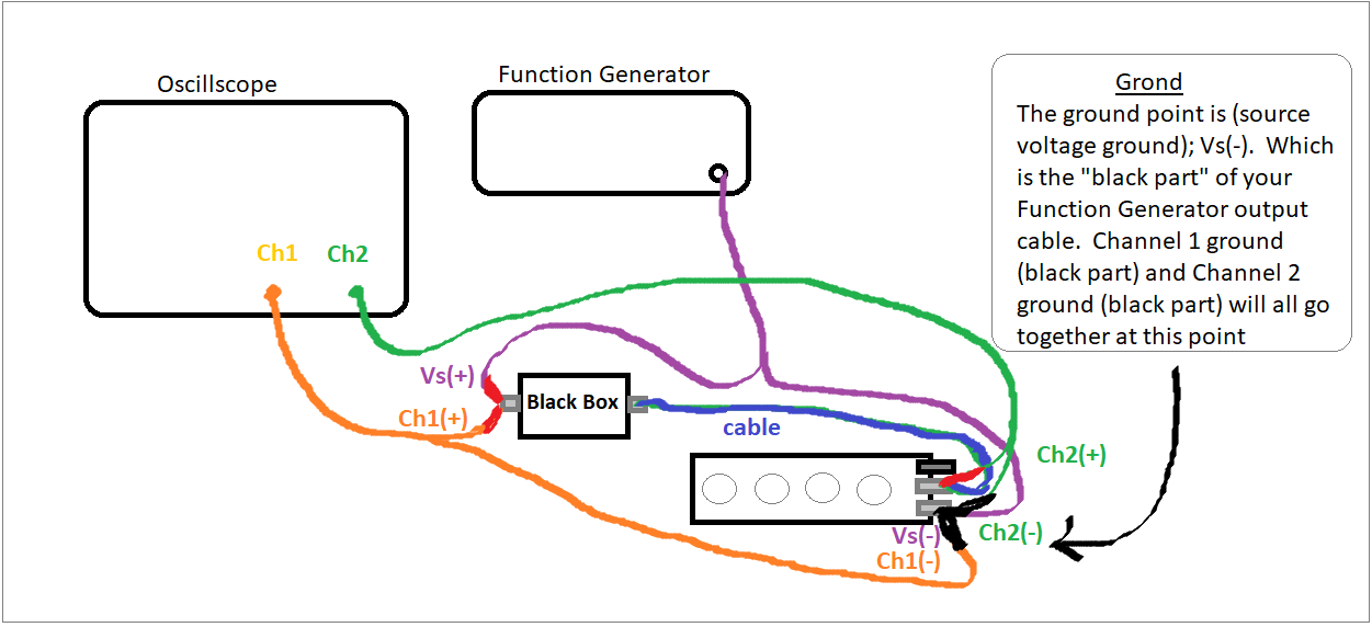
STEP 1 - Connection
Connect as following
1a) Function Generator output cable, connect the RED part to one end of the Black Box, and the BLACK part to the end of test resistor (decade box; or green resistor box, up to you)
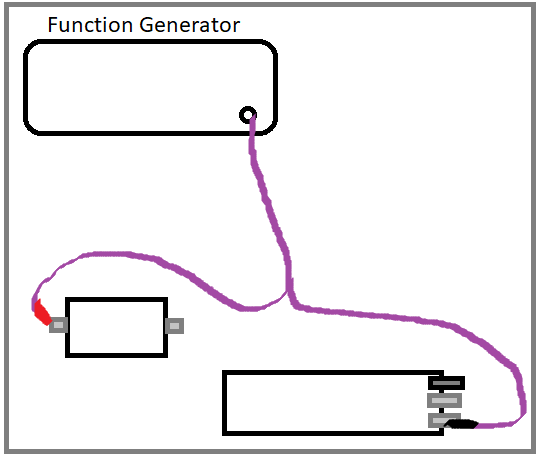
1b) Connect a short cable between the the other end of the Black Box to the other end of your test resistor (decade box)
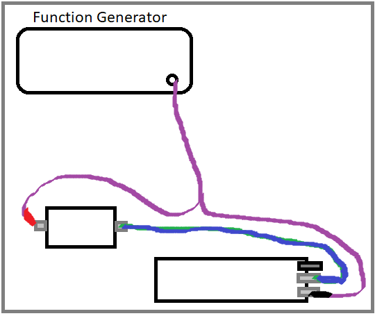
Your circuit is complete; next is connecting the Channel 1 and Channel 2.
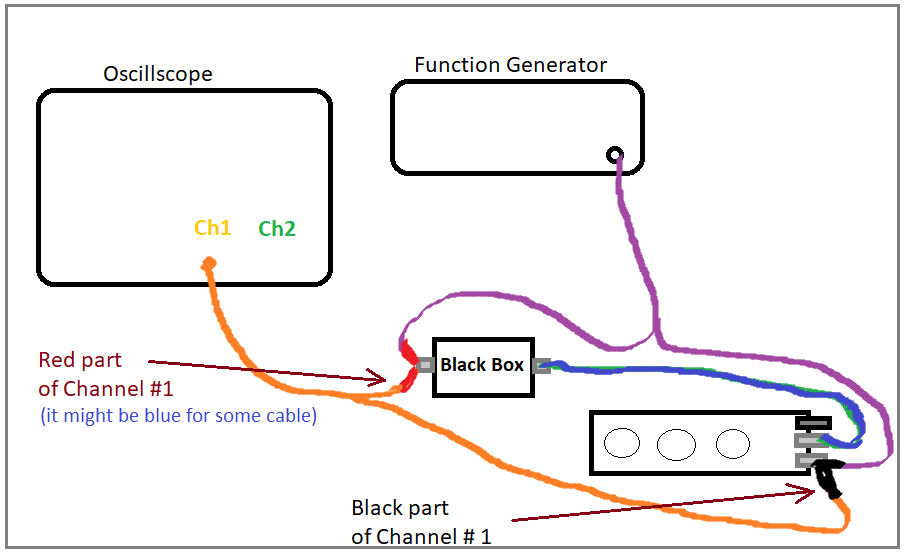
1c) Connect Channel 1 input cable from Oscillscope to Black Box and Test Resistor.
Remember, the RED part of the cable goes to the Black Box, the BLACK part of cable is your GROUND,
exactly same poisiton as you your Function Generator's output position.
same point as your Function Generator output calbe's BLACK part (this is your GROUND)
1d) For Channle 2, connect the BLACK part to your GROUND on the test resistor.
You should already have two black wire on top, so make the third one on top.
Connect the RED part on the other terminal of your test resistor. DONE
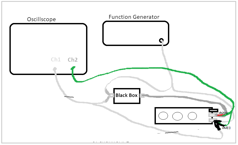
Remember, there should be 3 cable (Vs(-), Ch1(-), Ch2(-)) all attached on your GROUND terminal now.
STEP 2
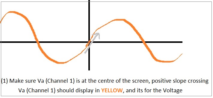
Channel 1 is measuring the VOLTAGE
Channel 2 is measuring the CURRENT (Vch2 / test resistor)
STEP 3
Set the decade resistor box to 20 ohm
Rtest resistor = 20 ohm
* You may use the Green Resistor Box (20 ohm is on there too)
STEP 4
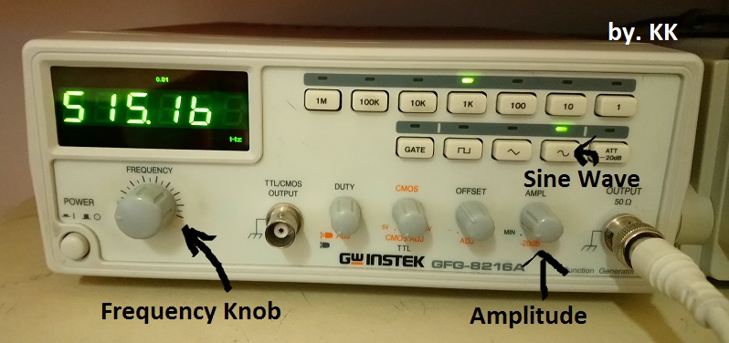
Set Function Generator to
- 5 V peak (or 10 V peak to peak), use Amplitude Knob
- Sine wave, Press Sine Wave button
- 500 Hz to start with (or any frequency you like), use Frequency Knob
STEP 5
Press AutoScale on the Oscilloscope
Push-in the button under Channel 1 and Channel 2 (centralize the wave)
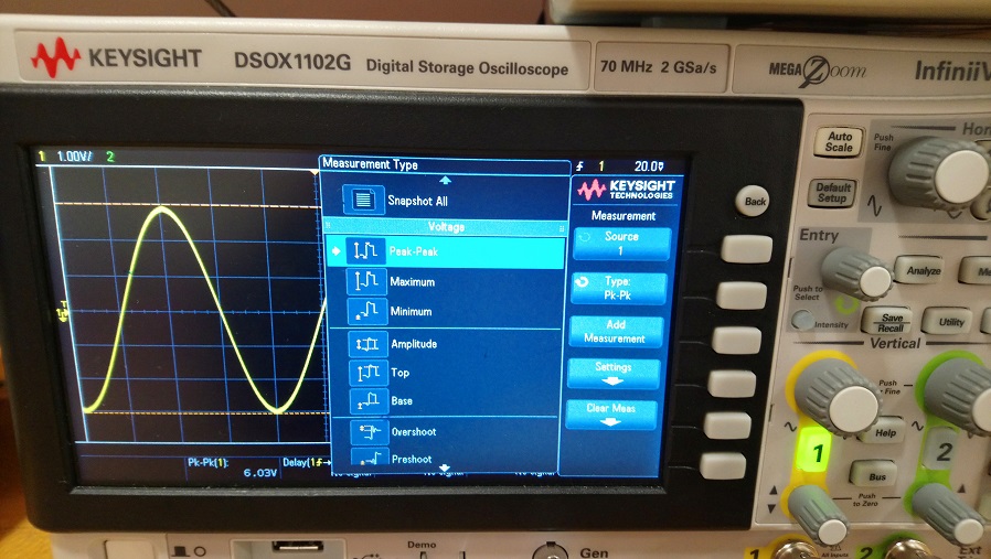
Press Measure on the Oscilloscope -- > Change Mode / Source -- > (1) Peak to Peak (2) Phase
STEP 6
Change the Frequency on the Function Generator
Analysis the wave (voltage leading or current leading?)
Record down frequency and phase value
STEP 7
Repeat STEP 6, you may need to Pres AutoScale everytime.
4 type, RC Series, RC Parallel, RL Series, RL Parallel
| RC Series | RC Parallel | RL Series | RL Parallel | |
| Inside Black Box Connection
|
 |
 |
 |
 |
| Waveform | Current is at the Left Side of the Voltage | Current is at the Left Side of the Voltage | Current is on the Right Side of the Voltage | Current is on the Right Side of the Voltage |
|
Waveform Result |
|
|
|
|
|
Frequency and Phase |
Increasing Frequency cause Phase Difference to Decrease F Φ
|
Increasing Frequency will cause Phase Difference to Increase F Φ |
Increasing Frequency will cause Phase Difference to Increase F Φ |
Increasing Frequency cause Phase Difference to Decrease F Φ |
|
New Example 2019
|
RCS Testing R = 1kΩ, C = 0.1uF, Series |
RCP Testing R = 1kΩ, C = 0.1uF, Parallel |
RLS Testing R = 1kΩ, L = 0.5H |
RLP Testing R = 1kΩ, L = 0.5H |
|
Operating Videos 2019 |
||||
|
Analysis Part 1 RC or RL Series or Parallel |
1) Its RC, b/c in the video, as you can see, the current is on the left side of voltage
2) Its Series, b/c in the video, as you can see, when frequency increase, the phase difference decrease. f1 = 500.65 Hz, θ = -79.67o f2 = 1000 Hz, θ = -58.09o
|
1) Its RC, b/c in the video, as you can see, the current is on the left side of voltage
2) Its Parallel, b/c in the video, as you can see, when frequency increase, the phase difference increase. f1 = 502.99 Hz, θ = -17.08o f2 = 1000 Hz, θ = -33.52o
|
1) Its RL, b/c in the video, as you can see, the current is on the right side of voltage
2) Its Series, b/c in the video, as you can see, when frequency increase, the phase difference increase. f1 = 482.37 Hz, θ = 40.85o f2 = 1.0071 kHz, θ = 59.81o
|
1) Its RL, b/c in the video, as you can see, the current is on the right side of voltage
2) Its Parallel, b/c in the video, as you can see, when frequency increase, the phase difference decrease. f1 = 482.15 Hz, θ = 25.56o f2 = 1.0071 kHz, θ = 15.15o
|
|
Analysis Part 2 Value for R, C, L |
3) Reocrd down the following 4 key data from the Oscilloscope and Function Generator under same frequency (I choice 1kHz) Va(ch1) , Vb (ch2) , θ and f Va (Ch1) = 10.3 V (peak to peak) Vb (Ch2) = 109 mV (peak to peak) Im = (109 mV / 2) / 20 Ω = 2.725 mA Phase θ = - 58.15o frequency f = 1008.1 Hz |
3) Reocrd down the following 4 key data from the Oscilloscope and Function Generator under same frequency (I choice 1kHz)
Va(ch1) , Vb (ch2) , θ and f Va (Ch1) = 9.8 V (peak to peak) Vb (Ch2) = 225 mV (peak to peak) Im = (225 mV / 2) / 20 Ω = 5.625 mA Phase θ = - 35o frequency f = 1059.5 Hz |
3) Reocrd down the following 4 key data from the Oscilloscope and Function Generator under same frequency (I choice 1kHz) Va(ch1) , Vb (ch2) , θ and f Va (Ch1) = 9.4 V (peak to peak) Vb (Ch2) = 59 mV (peak to peak) Im = (59 mV / 2) / 20 Ω = 1.475 mA Phase θ = 59.82o frequency f = 1.008 kHz |
3) Reocrd down the following 4 key data from the Oscilloscope and Function Generator under same frequency (I choice 1kHz) Va(ch1) , Vb (ch2) , θ and f Va (Ch1) = 9.2 V (peak to peak) Vb (Ch2) = 197 mV (peak to peak) Im = (197 mV / 2) / 20 Ω = 4.925 mA Phase θ = 15.02o frequency f = 1.0516 kHz |
|
Calcuation |
Vm = Va / 2 (if Va is p- to-p) = 5.15 V Z = (Vm/Im) Cosθ + j (Vm/Im)Sinθ = (5.15/2.725x10-3)Cos(-58.15o) + j (5.15/2.725x10-3)Sin(-58.15o) = 1.889x10³(0.5299) + j 1.889x10³ (-0.8480) = 1.00098x10³ - j 1.6018 x 10³ Where also Z = R + 1/(jωc) set real equal real, img equal img R = 1.00098x10³ * I assume Rtest 20Ω and internal resistance inside the Function Generator 50Ω is negligible compare to actual R. R >>20Ω ω = 2πf = 2π(1008.1) = 6333.45 1/(jωc) = - j 1.6018 1/c = -j*j (6333.45 * 1.6018 x 103) c = 1/(10133.52x 103) = 9.86823927e- 8 |
Vm = Va / 2 (if Va is p-to-p) = 4.9 V Y = (Im/Vm)Cosθ + j(Im/Vm) Sinθ = (5.625x10⁻³/4.9)Cos(-35o) + j (5.625x10⁻³/4.9) Sin(-35o) = (1.14795/103)(0.819) + j (1.14795/103)(-0.5735) = 0.00094017 - j 0.0006755 Where also Y = 1/R + jωc set real equal real, img equal img R = 1/0.00094017 = 1063.636 ω = 2πf = 2π(1008.1) = 6333.45 jωc = -j 0.0006755 c = 0.0006755/6333.45 = 1.06664507e-7 |
Vm = Va / 2 (if Va is p- to-p) = 4.7 V Z = (Vm/Im) Cosθ + j (Vm/Im)Sinθ = (4.7/1.475x10-3)Cos(59.82o) + j (4.7/1.475x10-3)Sin(59.82o) = 3186.44067797 (0.5027) + j 3186.44067797 (0.8644) = 1641.137 + j 2754.35 Where also Z = R + jωL set real equal real, img equal img R = 1641.137 ω = 2πf = 2π(1008) = 6333.45 jωL = j 2754.35 L = 2754.35/6333.45 = 0.4349 |
Vm = Va / 2 (if Va is p-to-p) = 4.6 V Y = (Im/Vm)Cosθ + j(Im/Vm) Sinθ ... ... Where also Y = 1/R + 1/ (jωL) set real equal real, img equal img R = ??? L = ??? |
|
Conclusion |
R = 1.00098x10³Ω (actual value is 1kΩ) C = 9.86823927e-8 = 9.868 x 10⁻⁸ F (actual value is 0.1 uF) RC - Series |
R = 1063.636Ω (acutal value is 1kΩ) C = 1.06664507e-7 = 1.07 x 10⁻⁷ F (actual value is 0.1 uF) RC - Parallel |
R = 1641.137Ω (actual value is 1kΩ, a little off) L = 0.43 H (actual value is 0.5 H) RL - Series |
R = ? L = ? Try it yourself... |
1) I still don't understand how to figure out if its RC? or RL?
Step 1 - Put Voltage (Va, Channel 1) at the centre of your Scope screen (middle).
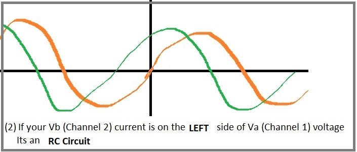
Step 2 - If the Current (Vb, Channel 2) is on the LEFT side of Voltage, its RC
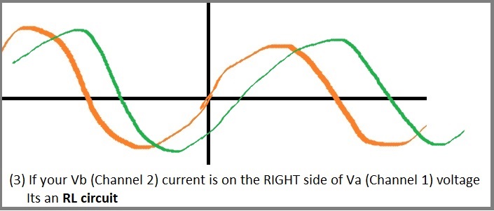
Step 3 - If the Current (Vb, Channel 2) is on the RIGHT side of Voltage, its RL
2) Calcuation : Z Impedance and Y Admittance
Series Circuit (both RC series and RL series)
use Impedance equation Z = (Vm/Im) Cosθ + j (Vm/Im)Sinθ
and it also equal
Z = R + 1/(jωc) ... if its RC
Z = R + jωL ... if its RL
Set Z = Z, real part equal real part, imaginary part equal imaginary part
Paralle Circuit (for both RC parallel and RL parallel)
use Admittance equation Y = (Im/Vm) Cosθ + j (Im/Vm) Sinθ
and it also euqal
Y = 1/R + jωc ... if its RC
Y = 1/R + 1/jωL ... if its RL
Set Y = Y, real part equal real part, imaginary part equal imaginary part
2) ω
ω = 2πf
3) Cosθ and Sinθ
The phase angle display on the scope is in degree (not rad).
Make sure you set degree on your calculator
4) What is j = ?
j = √(−1)
j2 = −1
We don't use i, because its the same symbol as we use for current. So we use j
5) Vb
Remember, Channle b (Vb) is in mv
m = 10-3, don't forget it
6) Unit
The unit for capacitance C is F (farad)
The unit for inductance L is H (henry)
7) The Phase Angle issue
(special thanks to Ashab)
"You said that the function of an RC is in series if the frequency increases and the phase difference
decreases. However in the example you have shown, the phase difference goes from -79.67 to -58.09.
Wouldn't this mean that thie phase inceases because -58 is higher than -79 becasue it is cloer to 0?"
f1 = 500.65 Hz, θ = -79.67o
f2 = 1000 Hz, θ = -58.09o
Yes, you are right, the phase angle is increasing.
But, becareful, we are looking at the phase difference between Channel 1 and Channel 2,
its not just the phase itself. Another way to said it, how far away in phase between Ch1 and Ch2.
To be safe and not to confused yourslef, you can use absloute on the angle and compare them after,
it will work for both RC and RL.
|θ1, -79.67o| > |θ2, -58.09o|
79.67o > 58.09o
And based on that, the phase difference is decreasing.
p.s. but don't use abs on phase when you calcuate the Z and Y,
also, the value for R, C, L are always positive.
8) Should I consider Rtest value for my R calculation?
(special thanks to Faiza)
This depend on your TA, follow your TA's instruction.
For my sections #1 and #7 (Kevin's), you don't have to do that.
Since as we discuss before, when you consider the magnitude of actual R, the Rtest is really small;
and that is why we use this tiny resistance value for the current (not affecting the voltage too much)
Notice, Rtest = 20Ω may be negligible compare to actual R, since R is much more bigger,
R >>>20Ω
However, if your TA want you include it, please do so.
The equation will be like the following:
When you to consider Rtest = 20
Z = (Vm/Im) Cosθ + j (Vm/Im)Sinθ
Z = R + 20 + 1/(jωc) ... if its RC Series
Z = R + 20 + jωL ... if its RL Series
Basically, just substract 20 from your final answer, done.
9) What is |Z| = ?
|Z| = |Vm/Im|
10) I don't know anything, I don't even know how to do lab 1, my partner did everything for me, do you think I can pass the test?
No, I don't think you can pass this test without any understanding. Please review and learn it.
Plus, we will have a long path to go in the future, include EES604, ELE302, ELE401, ELE504...etc
all Biomedical, Electrical and Computer student need to know the basic RC and RL. Don't give yourself any excuse, just shut up and study it.
Good luck !
1) Function Generator
- Frequency Knob (set the frequency)
- Amplitude (set the Amplitude)
- Sine, Square, Tri wave button
- OffSet Knob (make sure its push in, and you DON'T NEED IT for the lab test, its for DC off set)
2) Oscillscope
- AutoScale (Rerrange the wave)
- Measure & Entry Knob (Phase, Peak to Peak, Peak, Frequency)
- Vertical Position Knob (Centrialize the wave)
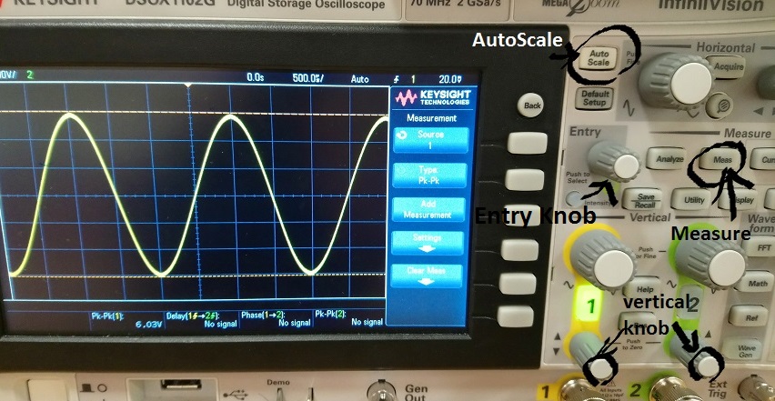
3) Display Phase
- Press Meas under Measure
- Rotate the Entry Knob, until you see Phase
- Push in the Entry Knob
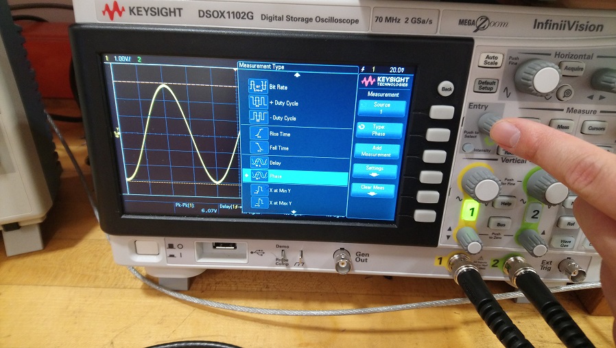
- Phase angle should display on the bottom of the screen, make sure is 1- >2
4) Remove Noise
Sometimes, the singal have very fuzzy noise, although it should't affect your result,
but you can try the following to removed the noise.
(Special thanks to Nabila and Oluwatoni)
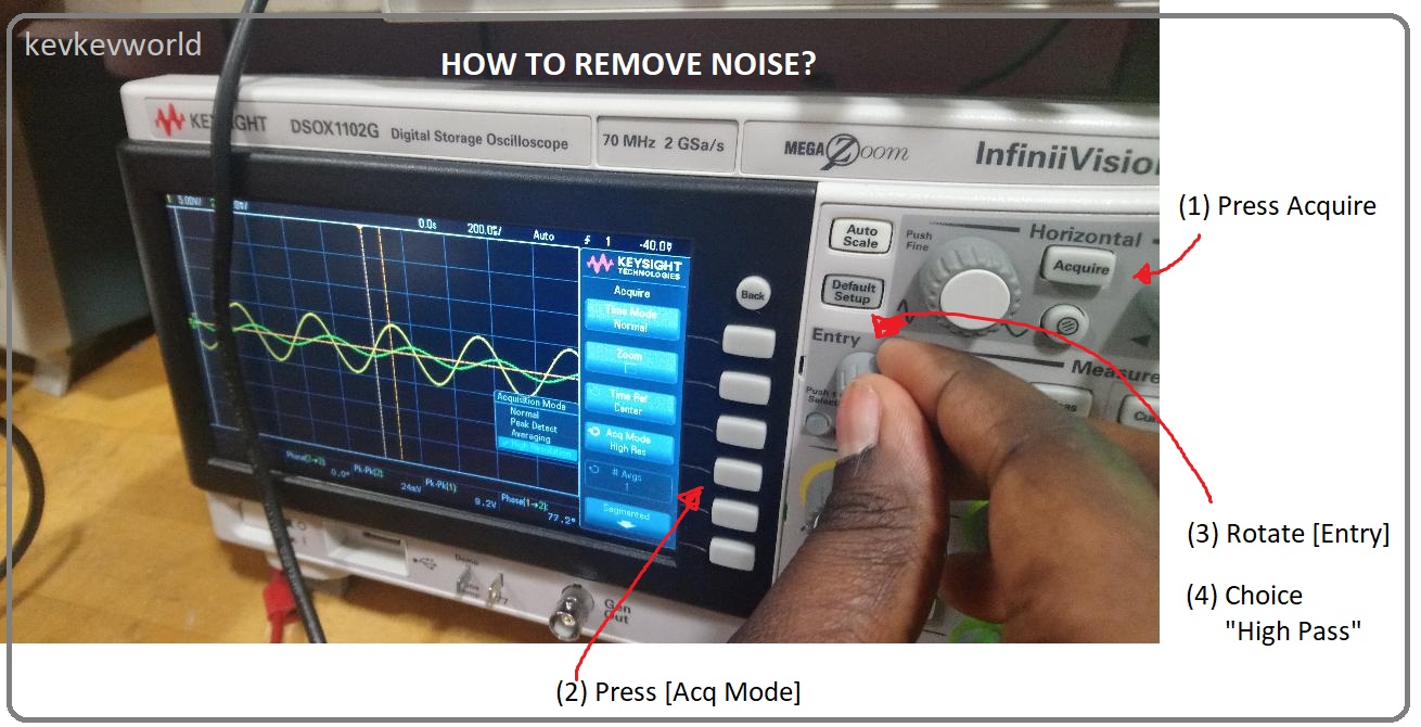
1- Press [Acquire] (under --Horizontal--)
2 - Press [Acu Mode]
3 - Rotate the [Entry], until you see the option on the scope changed to [High Pass]
4 - Choice [High Pass] by Push In the [Entry] Knob
5) Decade Resistor Box
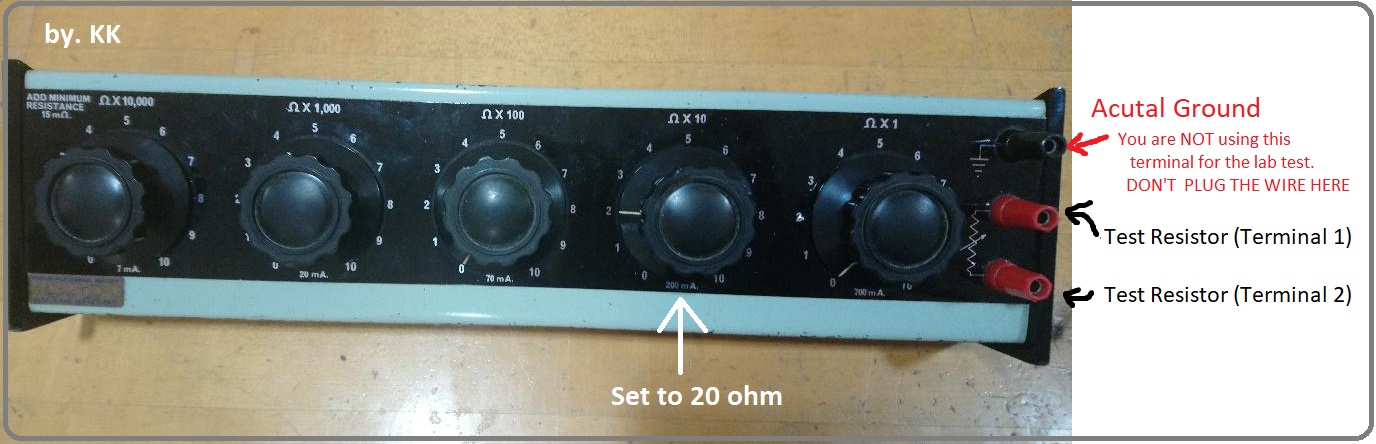
a) There is two terminals (red colour) on the decade resistor box, no (+) (-) .
b) Make sure you set the Decade to 20 ohm.
c) You are NOT using the Actual Ground Terminal on the top-right of the box, so DON'T PLUG IN ANYTHING. Thank you.
6) Run and Stop
As you can see on the lab tutorial, the phase kept changing, so as the voltage p-to-p value on the scope.
It might be hard to record down that value, so what you can do just Press the RUN/STOP button
When its STOP the button turn to RED
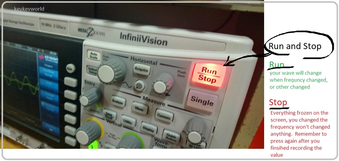
Please remember to Press Run/Stop button again (it should turn back to Green, running again) after you finished recording.
Want to try a QUIZ before the Lab Test?
OLDER VERSION (Black Box Tutorial, 2013)
http://www.kevkevworld.net/EE/blackbox
Any Question, feel free to email me or messanger me. Thanks.
Email: kevkev@kevkevworld.net
FaceBook: Kevin Tang


